Fluke: An Introduction of precision digital multimeters
High precision digital multimeters started to emerge for metrology use in the mid to late 1970’s. They became the preferred measurement tool for dc and low frequency ac electrical metrology. As a bonus, they were easy to use, multi-functional, and easy to automate. In certain applications they easily replaced the null detectors, yet their dc input amplifiers did not have the advanced design needed to fully match the null detector characteristics. In some critical respects they had serious shortcomings. One key area was the input bias current of the meter.
Bias current related errors
One of the non-ideal aspects of operational amplifiers such as those used in the input of a DMM is input bias current. This is a condition where current flows from the amplifier through the input terminals of the DMM. DMMs use CMOS amplifiers, which minimize this effect, but a current still exists on the order of picoamps. In voltage measurements where the voltage source is being measured, there is some source impedance in series with the voltage source. A small bias current through a small source impedance creates a negligible offset voltage. While this offset is in series with the voltage being measured, it has virtually no detrimental impact because it constitutes just fractions of nanovolts.
However, with certain measurement configurations where there is a sizeable source resistance from the voltage being measured (in the tens of k ohms), this resulting offset voltage due to the bias current could cause offset errors of several microvolts. This offset is directly in series with the measured voltage and is a serious error that must be dealt with if a DMM was to be used for critical measurements in such applications. Such an error could easily exceed the voltage measurement being attempted.
However, remember that this bias current characteristic was not a factor when using a null detector, so it was never something to be dealt with. Eliminating such errors requires extra measurement steps to compensate and remove these bias current offsets when using a DMM.
Use of voltage dividers
Electrical metrology uses primary level voltage standards for establishing traceability and working level voltage standards to calibrate working standard voltage sources. Because the voltage standards today are commonly at a 10-volt level, and the working standard voltage sources range from millivolt ranges up to a kilovolt range, voltage dividers are used to simplify intercomparing the sources to the 10-volt voltage standards. For example, a 100-volt source is divided by 10 to create a 10-volt level for comparing to the 10-volt working standard. Another example is calibrating a precision voltmeter at a non-decade voltage, such as 1.9 volts.
To create a precise voltage for such a test, a 10-volt voltage standard would be scaled by 0.19 ratio to create a 1.9-volt level for calibrating the meter. From these examples, ratios must both be decade values; that is, multiples of 10 (1:10, 1:100, 10:1 and100:1), as well as other variable ratios – such as from .999999 to 0.000001. There are many such dividers in common use.
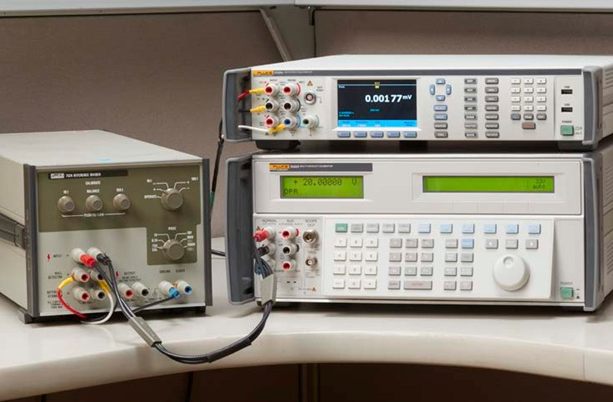
There are fixed ratio standards, such as the Fluke 752A Reference Divider, and variable ratio standards, such as the Fluke 720A Kelvin Varley Divider. These are regularly used to divide one voltage to match the level of a second voltage when doing calibrations across the voltages mentioned above.
The metrologist must confirm or adjust the dividers to insure they have the proper ratios for the intended calibration. These dividers must be balanced before use. Such balancing requires a null detector style of measurement to adjust for and confirm a proper ratio.
Divider balancing errors due to DMM bias currents
The most commonly used fixed or variable ratio standards are resistive dividers. When the dividers are balanced there is always a resis- tance between the two balancing points. This resistance is usually on the order of 25 kOhms to 40 kOhms. So, when you have maximum bias currents of 50 pA, the divider can generate undesired offset voltages of several microvolts. The metrology measurements using such divid- ers often measure voltage levels of zero volts to fractions of microvolts; therefore, these undesired bias current offsets have a serious effect.
Fortunately, techniques for eliminating these errors have been developed and are presented in white papers by Fluke metrologists. Updated ver- sions of those original papers are included on the Fluke Calibration website so you can refer to them for complete details about using a precision DMM in place of a null detector.
- Using the Fluke Calibration 8588A in place of analog null detector for self-calibration of the Fluke 720A.
- Using digital multimeters in place of analog null detectors for metrological applications
Recommended solutions to bias current offset voltages
The best way to correct this bias current issue is to properly select the DMM used for balancing and null detector measurements. Different DMMs have different designs and vary in their bias cur- rent situations.
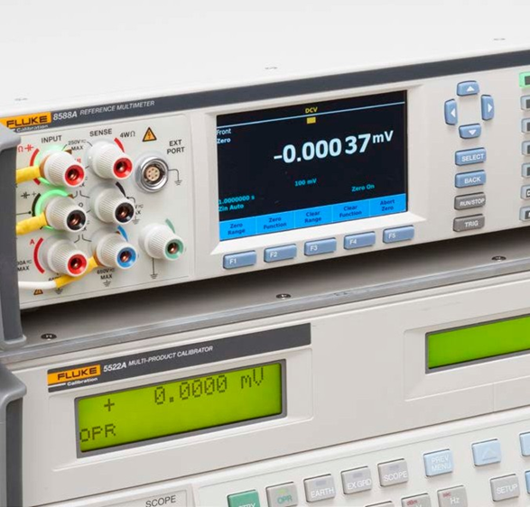
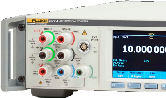
- Use a newer designed DMM: Since the 1970’s the precision DMM designs have amplifier circuitry with up to 50 pA of bias currents. The newest Fluke Calibration Reference Multime- ters (the 8588A and 8558A) have significantly less bias current, at 20 pA maximum. This bias current is also adjusted to be effectively zero pA when they are originally tested. This virtu- ally removes the bias current offset problem. Also, because the bias current changes very little over time, it remains near this level for an extended period into the future.
- Determine the offset and correct for it: In the initial balancing process, at the starting point where the DMM is connected to the divider and configured for the test, but before any external voltage source is to be applied, short the voltage input terminals of the divider and observe any offsets on the DMM. Any voltages measured will be the result of bias currents through the divider’s source impedance. If any offset is indicated, observe if the offset is relatively noiseless, and it is stable over time. If it is both stable and not excessively noisy, then it can be mathematically removed from the balancing measurements. The observed offset can be mathematically removed by doing a measurement offset correction on the DMM.
- Reject DMMS with unstable bias currents: A precision DMM can work very well for general metrology measurements. However, a small minority of these instruments have excessively noisy or unstable bias currents. These will not be able to be used to balance dividers.
- Expect many Fluke Calibration DMMs to have acceptable bias currents: Most Fluke Calibration Reference DMMs are adjusted for minimum bias current when they are manu- factured. As a result, you will see bias currents at a fraction of their maximum specification. So, with bias currents that show to be 5 pA or less no measurable offsets will show up in the offset test mentioned above.
- Periodically test for bias currents: It should be noted that a DMM’s bias current may slowly change over time. Regularly test the DMM for its bias current characteristics, or if it is not frequently used for balancing, then test before use, to see if the bias current is still acceptable.
Conclusion
The Fluke Calibration 8588A Reference Multimeter and 8558A Digital Multimeter are suitable replacements for analog null detectors, as was the previous generation 8508A Reference Multimeter. Appropriate corrections must be made for current emanating from the meter input terminals. Before any other digital multimeter is used as a null detector, the input bias current and other current sources must be considered to determine the significance of error generation to the circuit.
See more at:
Did you like the content? Did you take any doubts? Take advantage and check all the content and products available on the Datasonic website, a pioneer in cutting-edge technological equipment that stands out for its diversity of brands, models and especially prices is at your disposal, so you can take all your doubts, compare prices and finally, choose the best product for you. The Datasonic website has a wide portfolio and a range of varied products, all at your disposal. The Datasonic website is available to you 24 hours a day, 7 days a week. Just waiting for you to come and check out all the technology in equipment we provide for you and your company. What are you waiting for? Visit us right now.

Access: https://datasonic.com.br